

Why two PSUs? Three reasons:
1. I have a lot of crap, er, devices in The Beast, and I plan on adding a few more lights and fans, so I need more power.
2. I needed more power leads than a single PSU provides.
3. So I can tell people, "Yeah, I have a dual-power supply setup. I built it myself!"
PSU1 would power the motherboard, my primary HDD (in a mobile rack with a small fan at the back), and my Creative 48x CD-ROM. The processor fan and two LED lighted case fans, which are plugged directly into the motherboard, would also be drawing juice from PSU1.
PSU2 would power a second HDD in a mobile rack, my Sony 8x CD-RW, two to three additional lighted case fans, the 3.5" FDD, a drive bay USB/firewire/audio panel with lighted temp gauge, and any lighting kits I might install later (for now I have a single blue Sunbeam 12" CCFL in place).
But how to connect the two PSUs together was my challenge. Since PSU2 would be powering drives, and not just fans and accessories, I wanted both PSUs to come on when I pressed the main power button. The article showed two methods to accomplish this, either through use of a 12v relay or via a direct tap into the motherboard connectors of both PSUs. I settled on the latter method, since I intended to remove the unneeded motherboard wires from PSU2 anyway to save space, but I came up with a simple method of tapping into the wires on PSU1 without damaging them, leaving PSU1 intact to operate as a stand-alone unit should I ever need it.

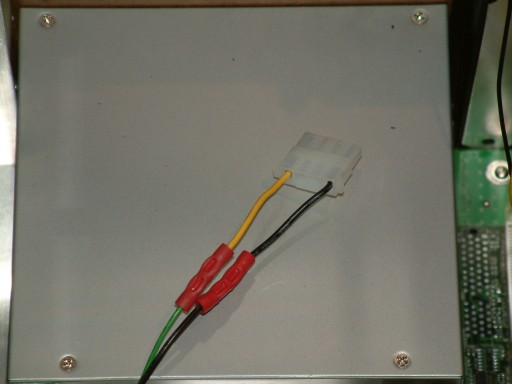
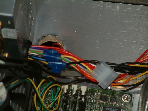
 The first thing I needed for this mod was a pair of HDD Molex connectors, one male and one female. Using in-line tap connectors, which can be obtained from Radio Shack or any electronics store, I connected one wire from the female Molex to PSU1s green #14 wire, and a second wire from the Molex to one of PSU1s black ground wires. I removed the two middle wires from the Molex connector, since I only needed two wires.
I prepared PSU2 by unplugging it and waiting an hour for the capacitors to discharge. I opened it up and snipped off all the unused motherboard wires, being careful to leave the green #14 and one of the black ground wires. I left these wires at their maximum length so they would stretch across my case to connect to PSU1. Then it was a simple matter to attach the male Molex wires to the ends of the green #14 wire and the ground which I had left in place, using insulated crimp-on butt connectors (click on the wiring diagram below for a larger version).


Now whenever I press the power button on the front of The Beast, both PSUs turn on, and my PC has plenty of power for all the crap, er, devices I have installed in it.


Send e-mail to the
Last Revision: 2005-10-08